Print Back
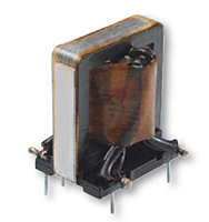
Triad gate drive transformers are used universally in all high frequency switching topologies to isolate the control circuitry from the line-connected switches. The windings are interleaved for the lowest possible practical leakage inductance. Turn ratios of 1:1 and 1:1.5 optimize coupling and enhance performance. Available with single or dual secondaries, these transformers constructed of UL rated 130 ºC materials are easily standardized at operating frequencies 200 kHz and beyond.
Switch Mode/High Frequency Gate Drive Transformers
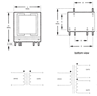
Outline Dimensions - Switch Mode/High Frequency Gate Drive Transformers
Unit of Measure
1 

Item #

Max. DCR 1-2

Max. DCR Gate

Min. ET Product

Max. Leakage

Min. Inductance

Overall Turns Ratio

GDE25-1 N/A 0.350 Ω N/A 0.350 Ω N/A 540 VµSEC N/A 2.5 µH N/A 0.680 mH N/A 1:1
GDE25-2 N/A 0.350 Ω N/A 0.650 Ω N/A 540 VµSEC N/A 2.5 µH N/A 0.680 mH N/A 1:1:1
GDE25-3 N/A 0.875 Ω N/A 0.350 Ω N/A 840 VµSEC N/A 3.5 µH N/A 1.50 mH N/A 1.5:1
GDE25-4 N/A 0.875 Ω N/A 0.650 Ω N/A 840 VµSEC N/A 3.5 µH N/A 1.50 mH N/A 1.5:1:1
GDE25-5 N/A 0.350 Ω N/A 0.875 Ω N/A 540 VµSEC N/A 3.5 µH N/A 0.680 mH N/A 1:1.5
GDE25-6 N/A 0.350 Ω N/A 01.75 Ω N/A 540 VµSEC N/A 3.5 µH N/A 0.680 mH N/A 1:1.5:1.5
Unit of Measure
1